EQMOD - Polar Alignment Checking using 3-Star Coordinate Transformation
The AFFINE/TAKI coordinate tranformation method basically is a SHIFT/ROTATE/SCALE coordinate transformation function.
Any SHIFT, ROTATION, SCALING on a given set of catalog points can be computed using the matrix transformation process.
Applying this on the 3-star alignment data (figure 1), we can compute for the mount's polar alignment discrepancy (shift/rotation) using the 3-star transformation
matrix data (c1,c2,c3,m1,m2.m3). c1-c3 being the catalog stars RA/DEC data, m1-m3 being the measured stars RA/DEC data captured during
the 3-star alignment process. Using arbitrary points (D1, D2) along the RA coordinate space, the coordinates of these points are
transformed (using AFFINE/TAKI) to Dx1, Dx2. Using these four points, D1,Dx1,D2, Dx2, we can compute for the polar alignment shift as
depicted by the blue NCP marker on the lower part of the image.
Figure 1: Diagram that shows the position of the polar axis right after the 3-star coordinate conversion
EQMOD - Polar Alignment Simulation using the 3-star/Nstar Affine Mapping DEC Drift Approach
1. The N-star to Polar Drift slope method basically mimics the standard "DRIFT Method" of Polar alignment as it computes for the drift without having to wait X minutes for a star movement on an reticle eyepiece. The N-star to Polar Drift slope method basically is a point-align- then-measure type of Polar Alignment error correction
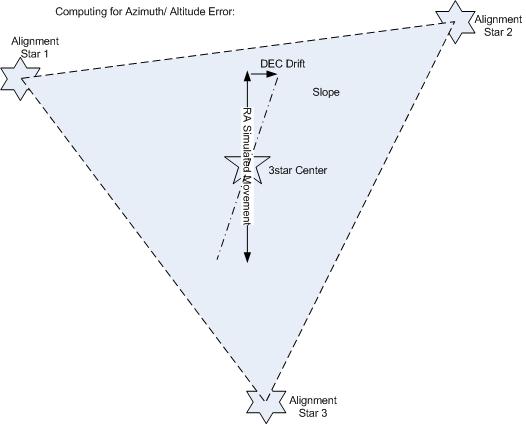
2. Just like the DRIFT Alignment method, to correct an axis error (azimuth or altitude), you need to choose 3 stars perpendicular to it. In this case, there should be a 3-star triangle measurement made available perpendicular to the axis to be corrected; Azimuth --> Meridian, Altitude --> Horizon.
Figure 2: Getting the drift data using the 3-star affine mapping method.
 |
Using the Simulator
A program was written to simulate the 3-star algorithm and the computation of the induced slope based on the Altitude/Azimuth shift errors.
You can download the application here: http://eq-mod.sourceforge.net/polar/Polar_NSTAR_Simulator.zip
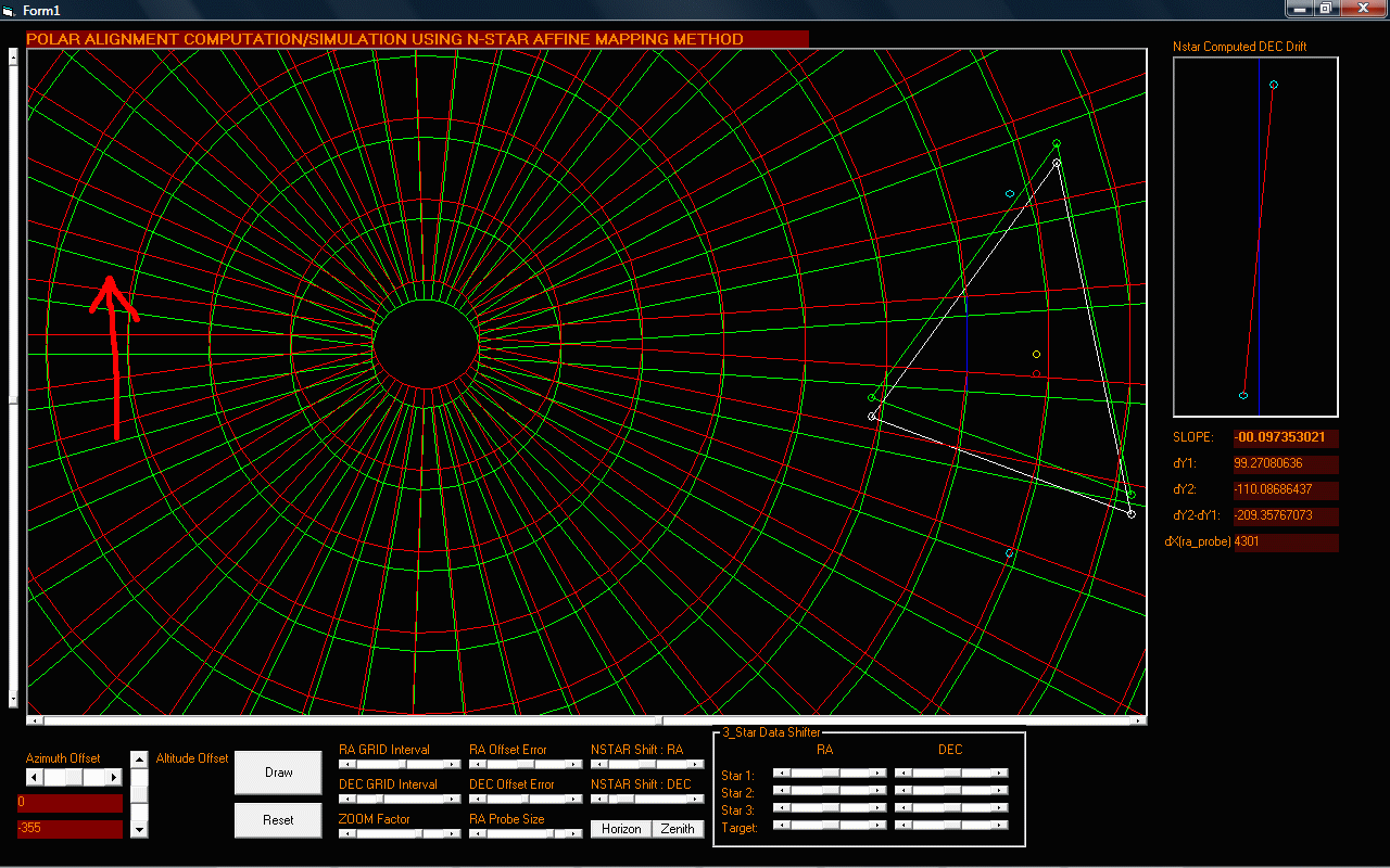
The screenshots below shows the simulation results of errors induced both on the altitude and azimuth axis:
LEGEND:
- The GREEN lines represents the RA/DEC grid of the Celestial Sphere
- The RED lines represent the RA/DEC grid of the equatorial mount
- A 3-star alignment representation can be found on the left side of the image with the corresponding shift as the result of the altitude/azimuth shift error.
- On the upper right portion of the image, a DEC DRIFT representation is shown with the corresponding slope computations. This is the actual computed drift based on the altitude/azimuth error.
- A RED arrow shows the induced error direction with respect to the celestial sphere axis.
- The term "RA_PROBE" here means the RA distance (in .144arcsec/step) between two DEC points that is used to compute for the DEC Drift.
Figure 3: Simulation result of an Altitude Error with the mount at 355 steps BELOW the celestial sphere (1 step = 0.144 arcseconds)
 |
Looking at the above results, you can actually confirm the induced drift as a result of the downward shift of the mount's altitude axis and its corresponding slope.
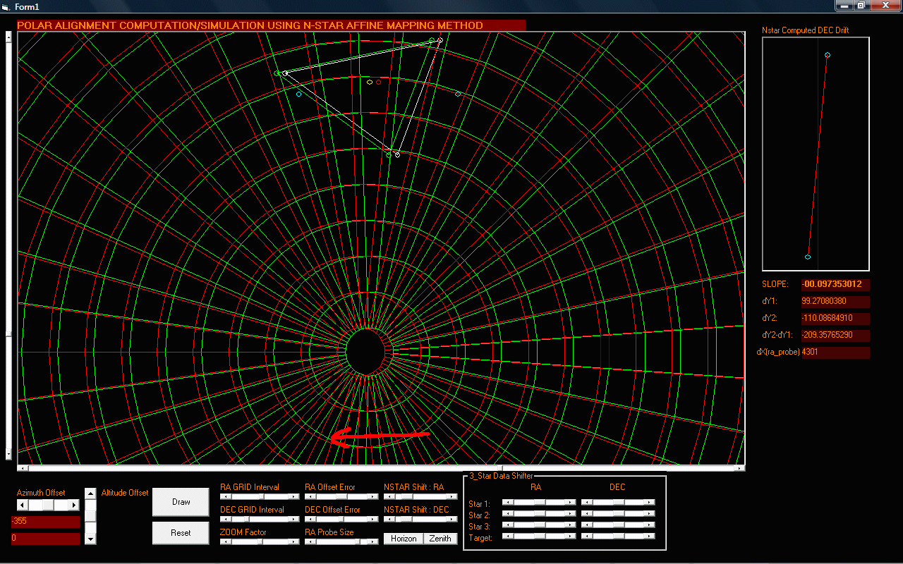
Figure 4: Simulation result of an Altitude Error with the mount at 355 steps ABOVE the celestial sphere (1 step = 0.144 arcseconds)
 |
With the same amount of error induced on the Mount Altitude shifted to the opposite direction, the same amount of slope on the opposite direction is measured confirming the consistency of the N-star drift method.
Figure 5: Simulation result of an Azimuth Error with the mount at 355 steps LEFT the celestial sphere (1 step = 0.144 arcseconds)
 |
This time the 3-star data is shifted above the celestial sphere axis in order to compute for the Azimuth Error. As mentioned, the 3-star/Nstar data should be perpenicular to the axis being measured.
Figure 6: Simulation result of an Azimuth Error with the mount at 355 steps RIGHT the celestial sphere (1 step = 0.144 arcseconds)
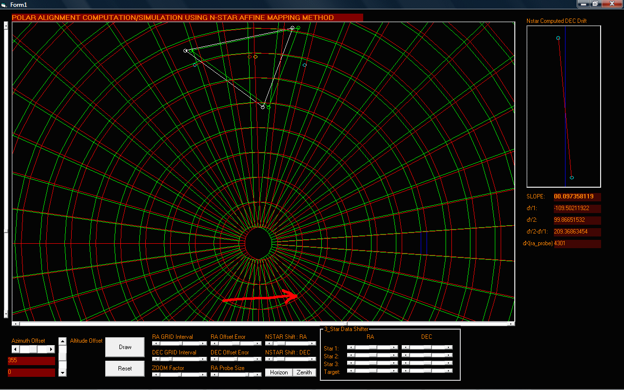 |
By looking at the slopes of the computed DEC drift, one can derive the amount of shift error on each axis.
Figure 7: Simulation result of an Azimuth Error with the mount's axis shifted to the LEFT the celestial sphere. THIS TIME the 3-star/N-star data is not perpendicular and lies along the az axis
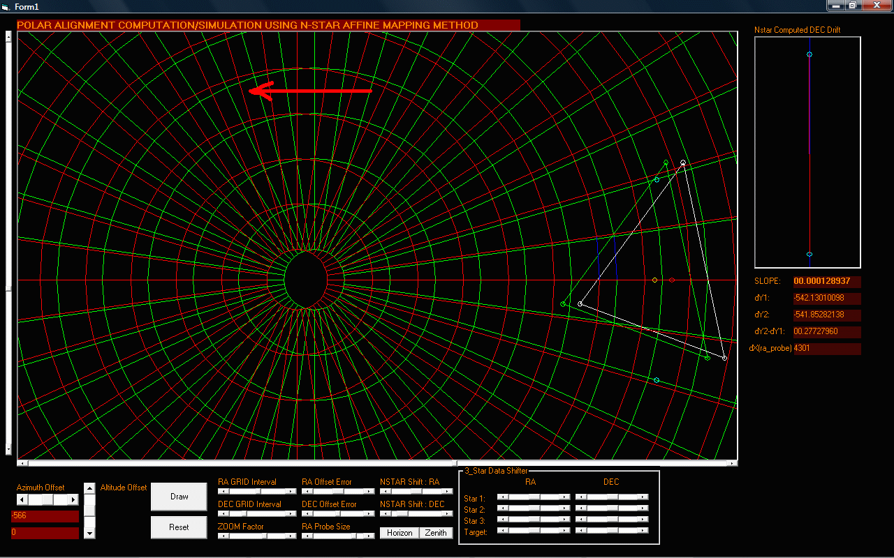 |
This is what will happen if we are using stars not perpendicular to the axis being measured. The drift influence is almost zero.
Figure 8: Simulation result of an Altitude Error with the mount's axis shifted to BELOW the celestial sphere. The same condition where the 3-star/N-star data is not perpendicular and lies along the alt axis
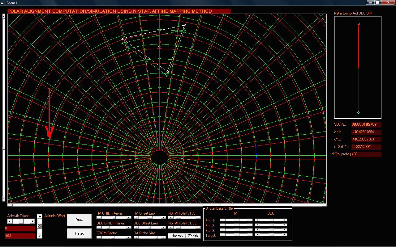 |
The same result on the drift which is almost zero. This basically confirms that all measurements should have the alignment stars perpendicular to the axis being measured.
Computing from a Virtual Horizon
Well, the good news is, the N-star data doesnt have to be on the Horizon as you can virtually shift the horizon to an angle where your N-star data is located and let the software compute for the azimuth/altitude errors from the virtual axis to the mount's true altitude/azimuth.
Figure 9: Computing for the altitude/azimuth shift from a virtual horizon.
 |
*You cant do this on the Standard Drift alignment method as you are dealing with a fixed mechanical position (that is the mount's azimuth being parallel to the true horizon).
If your N-star data is for example is measured from the east side let say 45 degrees above the horizon, the virtual horizon's altitude error can be computed. However, you need to measure another set of 3 stars perpendicular to it to get the virtual azimuth error and this is located 45 degrees from the other side of the meridian (west side). This means you need at least 6 stars to get the polar alignment. 3 stars from the east and another 3 from the west).
Figure 10: At least 6 stars needed to get both the Altitude and Azimuth errors
 |
3. The virtual horizon method works because in a spherical coordinate system there is really no concept of which is up,down,left, or right.
* You are required to "LEVEL" your mouunt when using the DRIFT ALIGNMENT method because of the fact that you are measuring from stars located at the meridian and the the horizon. The DRIFT ALIGNMENT method measurements will also be accurate if you measure from stars X degrees above the horizon if you also position the azimuth plate angle of your mount on the same X-degree angle -- However, this is mechanically impossible for most mounts and this is the reason why we are stuck on the horizon-meridian measurements.
4. This one is important:
As observed on the simulator, the drift data (either in the drift alignment method or in the N-star to Polar slope method) is easily influenced by both the altitude and azimuth errors if the star drift measurements are not perpendicular to their respective axis.
This means the drift you see for example at 45 degrees from the horizon is influenced both by the mount's altitude and azimuth error. It is impossible to get a polar alignment at this configuration.
For the DRIFT alignment method to work, best approach is to measure first at the meridian and cancel out the azimuth error. Then from there you can drift align even at 45 degrees to get to the altitude error (but this would require longer measurement time as compared to the one measured near the horizon).
For the N-star-->Polar method, this limitation can be easily overcome by virtually positioning the horizon to the same angle as n-star data (as explained in #3).
5. Accuracy: The N-star-->Polar will yield the same level(or even better) accuracy vs. the Drift Alignment method if;
5.1 The N-star alignment measurement is accurate (use a CCD or reticle eyepiece)
5.2 There is no mechanical/optical slop
5.3 Minimal Backlash errors.
5.4 In the simulator, there is a term called the ra_probe length. This is basically the RA distance between two points of DEC data that is needed to compute for the DRIFT Slope.
* The ra_probe length is equivalent to the Drift Alignment Method's RA movement per given drift measurement time
* The longer the ra_probe length value, the more accurate the slope measurement is. However, this is limited by the size of the N-star triangle. If the N-star alignment is accurate, even at short ra_probe values, polar alignment measurement will also be accurate.
6. Here is the best part. Once this method is perfected, it will now be possible to align even if the NCP/SCP is not visible. You only have to make TWO 3-star measurements on both side of the meridian.
VISITS since Mar 23, 2007


