Mount Periodic Error Correction through Variable Track Speed Adjustment
Mount periodic errors are caused by runout or gear teeth spacing discrepancies in the mount's RA wormgears. It becomes "periodic" in a sense that as the worm gear rotates, you encounter the same problematic part of the gear over and over again. The time period of the error depends on how long the worm gear completes one revolution. In the case for example on a EQ6 mount, the rotation cycle is 8 minutes.
Figure 1 shows a visible Periodic error as captured on a EQ6 with PEC/autoguiding disabled. The mount was left intentionally mis-aligned from the polar axis to make the PEs visible. As you can see the errors are very consistent. This was captured using a Logitech 4000 Webcam using K3CCD. The exposure was done roughly for 20 minutes.

Figure 1: Actual exposure of a star on a mount with PEs
If you have this kind of error on your mount, you basically lose the chance to get a decent image as the stars will always drift specially during a long exposure routine.
Possible Means of fixing/compensating for Mount Periodic Errors
One option is through GUIDING/AUTOGUIDING. The other option is by using a pre-recorded Periodic Error Correction pulses sent to the mount. Another option would be to make a variable speed adjustment on the RA motor on specific RA wormgear positions. Each of them attempts to make the mount tracking/ rotation as constant as possible with respect to the Sidreal rate.
Figure 2 shows a simulated graph comparison in terms of arcsecond discrepancies on each correction option.
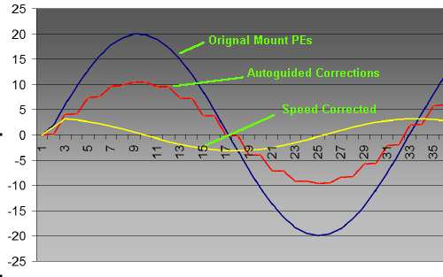
Figure 2: Simulated PE graph
The blue graph is a 'simulated curve' of a typical mount's PE. The red graph shows a typical correction curve on a "Autoguided/PEC enabled" mount. The yellow graph shows a 'simulated curve' for a mount corrected through variable speed adjustments.
TYPICAL DISCREPANCIES ON AUTOGUIDING/PEC methods
A standard autoguiding procedure is made by pointing a separate scope (guidescope) with a CCD based webcam/video camera to a reference star. The software that captures the reference star image on the webcam records the pixel position of the star and monitors any movement with respect to the surrounding ccd pixel exposure. This is done while the mount is tracking at the sidreal rate. The software then sends a tracking "correcting pulse" to the mount to put back the star back at the original pixel position on webcam/videocamera CCD. The corrections are done on a regular interval depending on when the camera can give a single frame exposure. Most setups are tracking on faint stars that the software needs to put the camera in long exposure mode (typical 1 to 2 seconds or more). That means tracking corrections are done every 1 or 2 seconds after each camera frame capture. Now what errors can come out from these scheme ?
Figure 3 Shows a simlated curve of the autoguided/PEC graph

Figure 3: Simulated autoguiding corrections graph
There are four autoguiding correction signals sent to the mount
RA+ : Move to the east faster than the sidreal rate
RA- : Move to the west slower than the sidreal rate
DEC+ : Move the scope to the North
DEC- : Move the scope to the South
Each of these lines generate a pulse with a 'specific' duration to the mount. The width of the pulse determines how long a 'correction' has to be made and it usually lasts 1 to 2 seconds. The corrections are done on some fixed autoguiding rate (0.25, 0.5, 0.75 of the Sidreeal).
If you look at figure 3, guide corrections are sent in intervals (not continuous). A case for example when the guidesoftware activates RA- (RA- ON on the graph), the slope/drift in terms of arcseconds discrepancy becomes less on a 'rising part' of the periodic error. But when the guide software releases the RA- signal (RA- OFF on the graph), the slope/drift tends to follow the original slope of the Periodic Error. Because these signals are sent in intervals, you are actually still introducing the error in between the time were no guide signals are sent causing the drift error in terms arcseconds to increase. Overall, the autoguiding approach basically reduces the drift but only as much depending on the interval setting, camera exposure, etc. The same case also happens on PEC enabled mounts which are 'manually' trained. PEC basically sends the same (although pre-recorded) guide corrections (and usually at a fixed PEC guide speed) to the mount.
Technically in a physical sense, the current guiding method is like bashing the graph error with a 'nail hammer' to make the bumps 'smaller' where each hammer stroke becomes analogous to a guide correction pulse sent to the mount.
RA MOTOR VARIABLE SPEED ADJUSTMENT for Periodic Error Correction (VS-PEC)
Figure 4 Shows a 'simulated curve' for mounts implementing PE corrections using variable speed adjustments.

Figure 4: Simulated curve on mount's implementing PE corrections through variable speed adjustments
In this case, the corrections are made by varying the speed of the RA motor at specific wormgear positions. The corrections are sent in intervals and the RA motor will assume that corrected speed until the next interval. The computations for the new speed is made by looking at the slope of the mount's Original PE graph. If the slope (blue graph) is higher, then the RA speed should be lower than the sidreal rate, if the slope is low, the RA speed should be increased. With this approach, even if the corrections are being sent in intervals, the corrections are implemented continuously (or until the slope on the original PE changes).
So instead of RA+ ON, RA+ OFF, RA- ON,RA-OFF, DEC+ ON, DEC+ OFF, DEC- ON, DEC- OFF guide commands, the correction commands are sent as;
RA- (0.1) --> RA- (0.2) --> RA+(0.1) --> RA+(0.3) --> RA(sidreal rate) --> RA-(0.2) --> RA- (0.1) ---> and so on
Accuracy usually increase depending on the interval of sending the speed adjustments.
Speed adjustment values could be anywhere between (+/-) 0.1 to 0.9 (at increments of 0.1) of the sidreal rate.
OTHER OPTIONS FOR VARIABLE SPEED RATE ADJUSTMENTS (autoguiding-vs-pec in one)
It is also possible to have a 'fixed' correction table for a mount based on wormgear encoder values but this requires that the mount has 'readable' encoder position parameters instead of RA/DEC/ALT/AZ values.
This approach uses the standard autoguider software to capture the PEs of the mount, then it records the RA motor encoder position of each slope sample.
A 'VS-PEC' player is then used to send to the mount 'realtime' the guider pre-computed corrections based on previously captured PE graph and motor encoder values. This is done while the mount is tracking at the sidreal rate.
The autoguider is only needed during the training/PE capture process and you can synchronize it to any bright star instead of some faint star usually limited by the position of your autoguider setup. That means you can point your scope to any part of the sky which has a bright star on it and do the training process from there. Then during the VS-PEC playback portion, you only need to re-point the scope to the part of the sky you wish to image.

As the wormgear rotates, the speed correction data is sent to the mount realtime. The actual time when the speed correction change will be sent would depend on the current RA motor encoder value which specifies the current position of the wormgear. The player should read these values at a fixed interval and used that as a basis on when to send the next speed correction data.
This is all done while the mount is tracking at the sidereal rate and the main scope is imaging - and at this point no guidestar is required during imaging.
With the proper application. PE Slope computation, stepper encoder access, and mount speed adjustment capability, the correct graph (yellow) on figure 4 can be easily achieved.