EQMOD Stepper Encoders to RA/DEC/ALT/AZ Conversion Test program
This program contains information on how to convert the stepper motor encoder values to the corresponding RA/DEC Equatorial Coordinates and ALT/AZ Coordinates. It shows also a couple of routines that allows you to generate the stepper encoder values from these two astro coordinate system. Figure 1 is a screen shot of the the VB test program;

Figure 1: Screenshot of the Encoder to RA/DEC/ALT/AZ conversion test program
The program uses the EQContrl DLL driver for connecting to the EQ mount and ASCOM's Astro32.dll for the RA/DEC/ALT/AZ computations. You can actually use the routines here to write your own ASCOM driver as its already being patterned for ASCOM communication.
Before you can use the program and the EQControl.dll driver, you need to modify your mount as described here.
The program initally connects to the mount via the EQControl.DLL and reads every 200 milliseconds the ra and dec motor encoder values and converts them to DEC and Hour Angle (HA) values. Using the site information coordinate values, the encoder positions are converted to RA/DEC, ALT/AZ coordinates. The converted values are updated on the screen application every 1 second. Check routines were also included that verifies if the conversion is correct or not. This is done by reconverting for example the ALT/AZ values back to RA/DEC and visually compare the result with the original values. The ALT/AZ and RA/DEC values are also converted back to motor encoder values just to confirm visually if the conversion process for the encoder values is correct.
The current motor shaft position is visually represented by a pie chart.
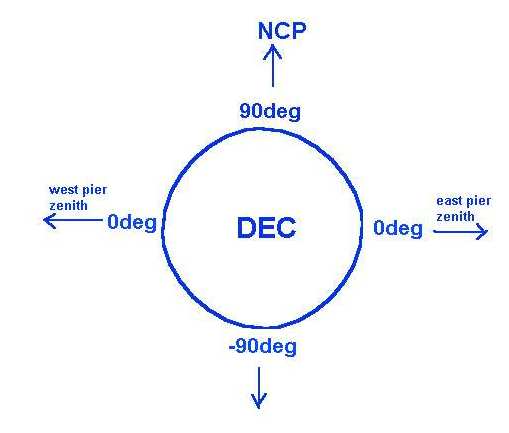
If you notice, the derived DEC Encoder values may have actually two sets of values. Both are correct except the other one would require you to rotate the motor on the opposite direction and eventually it will arrive at the same physical position. As to when to use any of the two values would depend on the position of the Pier (either west side or east side).
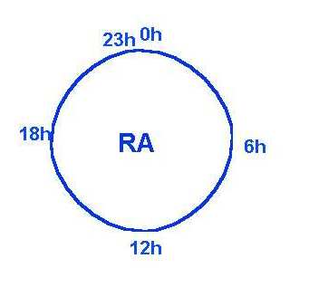
Figure 2 and 3 shows a visual representation of the stepper motor positions relative the the angular hour and degrees values;

Figure 2: RA Shaft position in "Hour" format

Figure 3: DEC Shaft position in degrees format
The position representation of the DEC shaft is identical on both sides (-90 to 90) as it only varies on the East/West Pier side position.
DOWNLOAD
You can download the application here (including SOURCE CODES);
The program source is pretty much commented for other explanations / details on the implementation.
USAGE
The program is very simple. Just connect your modded mount to your PC via RS232C and put the paddle mod switch into "Extended mode". Load the EQradec.exe program, specify your location's coordinates, specify the COM port and then click "Connect". If the motors are already initialized prior to the connection process, the program will just load the current ra/dec encoder values and display the results of the computation. You can actually exit the program and still remember the last position of the motors as long as you dont press the "Init motor coils" button but this assumes that the motors are already initialized either by your handpaddle or by a previous test run. If there are no coil initialization that took place prior to the test, then you need to put the mount at the park position (ra/dec pointed north) , click on the Connect Button then click the "Init Motor Coils button". At this point the application will set the encoder values to the NCP park position. You can then verify the computations by moving the mount with the slew buttons found on this program. The slew rates can be adjusted to any value between 1 to 800.
To exit, just click on the "Stop/Disconnect" button
The site location values are not saved although you can modify the code to have a more permanent setting.
The code also assumes a North Hemisphere orientation.
You need to modify some of the functions for a south hemisphere orientation.
DISCLAIMER:
You can use the information on this site COMPLETELY AT YOUR OWN RISK. The modification steps and other information on this site is provided to you "AS IS" and WITHOUT WARRANTY OF ANY KIND, express, statutory, implied or otherwise, including without limitation any warranty of merchantability or fitness for any particular or intended purpose. In no event the author will be liable for any direct, indirect, punitive, special, incidental or consequential damages or loss of any kind whether or not the author has been advised of the possibility of such loss.
WARNING:
Circuit modifications implemented on your setup could invalidate any warranty that you may have. Use this information at your own risk. The modifications involve direct access to the stepper motor controls of your mount. Any "mis-control" or "mis-command" / "invalid parameter" or "garbage" data sent to the mount could accidentally activate the stepper motors and allow it to rotate "freely" damaging any equipment connected to your mount. It is also possible that any garbage or invalid data sent to the mount could cause its firmware to generate mis-steps pulse sequences to the motors causing it to overheat. Make sure that you perform the modifications and testing while there is no physical "load" or dangling wires on your mount. Be sure to disconnect the power once this event happens or if you notice any unusual sound coming from the motor assembly.