EQMOD - Polar Alignment procedure
Here are the basic steps to measure the polar alignment error using EQMOD's N-star data
1.Perform a 6 star alignment procedure. (3 stars from the eastern side of the meridian and another 3 on the western side).
2.Choose and Display EQMOD's polar alignment window by cycling through the display+ button.
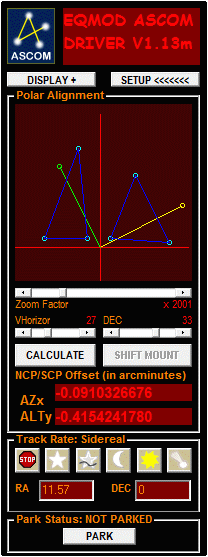
This window will display Polar Alignment N-star screen and map out the location of the alignment stars as represented by the cyan circles (figure 1)
Figure 1 :N-star alignment stars (cyan circles)
It will also display the two drift probes as indicated by the yellow and green circles (figure 2).
Figure 2: Drift probes indicated by the yellow and green circles.
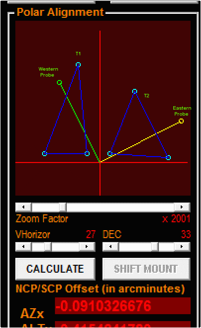
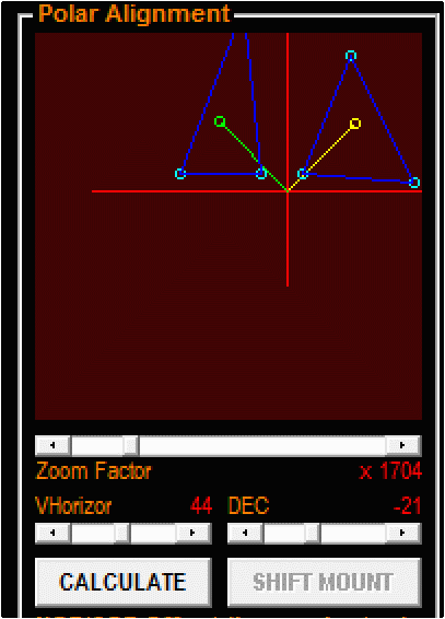
3.Confirm if the Drift probes (yellow and green circles) fall withing the 3-point triangle area.(figure 3)
Figure 3: Screenshot showing location of the drift probes inside the N-star triangles.
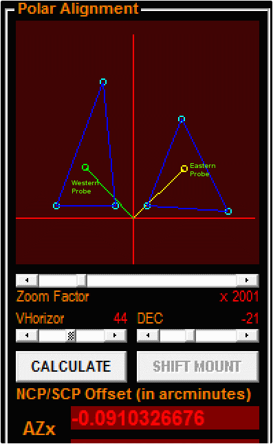
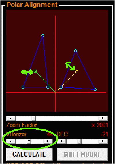
If not, make some adjustments on the location of the probe by adjusting the "VHorizon" and "DEC" sliding bars.
- The VHorizon sliding bar adjusts the RA component of the two drift probes (figure 4)
Figure 4: VHorizon bar adjustment
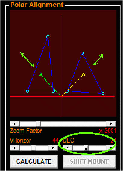
- The DEC sliding bar adjusts the DEC location of the two Drift Probes (figure 5)
Figure 5: DEC bar adjustment
4. The plot display can be shifted by dragging the mouse on the display itself.
Figure 6: Shifting the display using the mouse
The mouse image shift function plus the zoom bar will allow you to conveniently position the triangle data on the screen (figure 6).
5. Once you are able to position the drift probes within their respective N-star triangle, click on the calculate button.
Driver will then automatically compute for the polar alignment errors.
6. TO Follow: Mount movement using the shift mount button.