DISCLAIMER:
You can use the information on this site COMPLETELY AT YOUR OWN RISK. The modification steps and other information on this site is provided to you "AS IS" and WITHOUT WARRANTY OF ANY KIND, express, statutory, implied or otherwise, including without limitation any warranty of merchantability or fitness for any particular or intended purpose. In no event the author will be liable for any direct, indirect, punitive, special, incidental or consequential damages or loss of any kind whether or not the author has been advised of the possibility of such loss.
WARNING:
Circuit modifications implemented on your setup could invalidate any warranty that you may have. Use this information at your own risk. The modifications involve direct access to the stepper motor controls of your mount. Any "mis-control" or "mis-command" / "invalid parameter" or "garbage" data sent to the mount could accidentally activate the stepper motors and allow it to rotate "freely" damaging any equipment connected to your mount. It is also possible that any garbage or invalid data sent to the mount could cause its firmware to generate mis-steps pulse sequences to the motors causing it to overheat. Make sure that you perform the modifications and testing while there is no physical "load" or dangling wires on your mount. Be sure to disconnect the power once this event happens or if you notice any unusual sound coming from the motor assembly.
In order to connect a PC/Laptop directly to the EQ mount a PROPRIETATRY interface device is required. This device is refered to as an EQDIRCT and is designed soley for use with Skywatcher mount. Standard "off the shelf" Connection must be made through such a device NEVER CONNECT DIRECLY YOUR PC DIRECTLY TO THE MOUNT. Please take utmost caution if using "off the shelf" serial/RS232 cables, the connectors on the mount, despite being familar types are not standard R2332 or ethernet connections.
For those who wish to build their own mount interface there are three EQDIRECT options presented here.
- EQDIRECT-USB
- EQDIRECT-RS232 - This provide and RS232 connection to a PC with built in RS-232 port or that is using a USB-RS232 Serial convertor.
- EQDIRECT-BT - requires the PC to have
a Bluetooth interface (either internal or external dongle)
EQDIRECT-USB
The most popular type of EQDIRECT is the EQDIRECT-USB. This cable will plug into the mounts handset connector at one end and into a PC USB port / hub at the other.
The starting point for an EQDIRECT-USB is an off the shelf USB-TTL cable. Such a cable is avilable from FTDI called the TTL232R, and comes integrated into a USB cble and connector. Please be aware that FTDI produce a similar product, the TTL232R3V3, but due to lower signaling voltages this will not work with the EQ6Pro, HEQ5 type mounts (the mount expects to see a minimum 4V active high signal). The AZ-EQ6GT and EQ8 mounts have a 5V tolerant 3.3V signaling interface and so TTL232R3V3 or TTL232R can be used.
The USB-TTL cable must then be adapted to match your mount's handcontroller connector. Any connector that came with the USB-TTL cable must be removed as it will not be suitable as is.
- Connect or splice a 9 way "D" type plug/cable to the flying lead of the TTL232R. The connections are as follows:
- Solder Pin 6 of the 9 way D-type Plug to the Orange wire (TXD).
- Solder Pin 9 of the 9 way D-type Plug to the Yellow wire (RXD).
- Solder Pins 4 & 5 of the 9 way D-type Plug to the Black wire (GND).
HEQ5 / AZEQ6-GT
- You will need to splice a RJ45 cable to the flying lead of the TTL232R. Connect as follows:
- Solder Pin 4 of the RJ45 to the TTL232R Black wire (GND)
Solder Pin 5 of the RJ45 to the TTL232R Yellow wire (RXD)
Solder Pin 6 of the RJ45 to the TTL232R Orange wire (TXD)

AZ-GTi
- You will need to splice a RJ12 cable to the flying lead of the TTL232R. Connect as follows:
- Solder Pin 5 of the RJ12 to the TTL232R Black wire (GND)
Solder Pin 2 of the RJ12 to the TTL232R Yellow wire (RXD)
Solder Pin 4 of the RJ12 to the TTL232R Orange wire (TXD

A driver is installed on the PC and the TTL232R appears as a standard windows COM port. There is an additional advantage in that unlike many usb-serial devices the com port number of the FTDI device, once assigned, will not change when plugged into a different physical USB port.
Data sheet here: http://www.ftdichip.com/Support/Documents/DataSheets/Cables/DS_TTL-232R_CABLES.pdf
EQDIRECT-RS232
The
EQDIRECT-RS232 benefits from being able to support much longer cable
runs between the PC and the EQDIRECT device (up to 20m max).
For the EQDIRECT-USB the maximum length is 5m (USB standard),
although this range can be extended using powered hubs. Please note
that for both types the cabling between the EQDIRECT and the
mount should be kept to 2m maximum (prefreably as short as is
convenient).
Also
be aware that when using an EQDIRECT-RS232 device in combination with a
usb-232 convertor fitted to the PC you should make sure the usb-232 convertor is of a
type that supplies true (-9V,+9V) RS-232 signals.
Figure 1 shows a diagram that will allow you to directly connect your PC to the Mount's DB9 Handcontroller Port. The port contains both the 12V power lines and the two TTL level serial data lines. It allows the user to send the commands from the PC's serial port to the mount's handpaddle DB9 port. The circuit utilizes two major components; a RS232C-TTL converter (MAX232) chip and a 5 Volt voltage regulator (7805) that supplies power to the max232 chip. The 7805 source of power comes from pins 1 and 8 of the mount's DB9 connector. Extra care should be provided in avoiding these lines to be interchanged/shorted to the TTL level lines (pins 9 and 6). Pins 5 and 4 are ground pins.
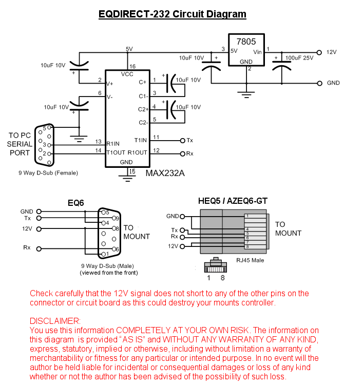
Figure 1: Circuit Diagram for Direct PC access through the mount's DB9/RJ45 connector
EQDIRECT-BT
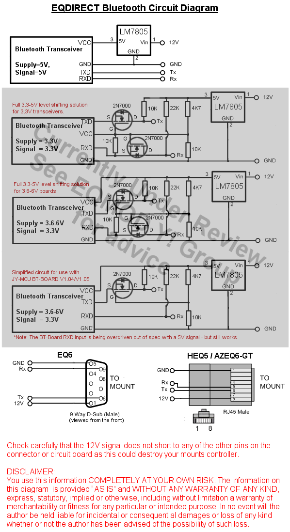
A wireless EQDIRECT can be constructed using a Bluetooth Slave Transceiver unit. These unites can be found on Ebay, often shipping direct from China. Look for units that contain a reference to HC06 or HCO5 in their description/documentation, HCO6 boards can be either Master or Slaves - you need a Slave device. An example of what you are looking for is shown below.
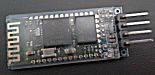
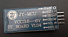
The units themselves consist of a transceiver module attached to a base board (sometime refered to as a backplane). The transceiver modules themselves are 3.3V devices but the base boards add a little extra functionality such as a wider power supply range, status LED, in some cases I/O vlotage mapping to other levels such as 5V TTL or RS232, and a header connection. If you wish you can use a transceiver module by itself to make your EQDIRECT-BT but it is usually no chaepar than buying a combined transceiver/baseboard unit which is easier solder/connect due to its header. Be aware that the baseboards are also available without transceiver modules attached - so be careful when buying..
The simplest EQDIRECT to construct is one based on a "5V TTL signaling, 5V power" bluetooth unit as these can interface directly with the mounts communications lines. However, these devices tend to be more expensive and harder to find.
3.3V
units are more common, some will allow a supply of to 6V but Tx/RX
signaling is still expected to be at 3.3V. The mount motor
controller should require a minimum "high" signal of 4V (min. active
high) on its
Rx data pin and so some extra circuitry is
required to interface the mount to this type of bluetooth unit.
This said the unit I tested (and shown above) works flawlessly without
needing these additions even though I can't explain why!
You will need a Bluetooth enabled PC or an external Bluetooth USB dongle. On initial bluetooth pairing you may be required to enter a pair code (default is usually "1234" unless your specific transceiver documentation specifies otherwise). If presented with a pair of virtual COM ports then use the one labled "Outgoing" as the EQDIRECT port.